 Pomanique Electric Co., Ltd.

Controller description
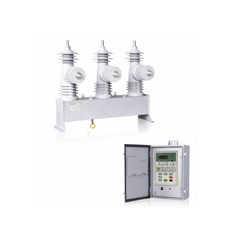
Controller
The Microprocessor Based controller provide protection, control, monitoring, instrumentation and metering with integrated input and output logic, data logging & fault reports.
Communication access to controller functionality is via electrical RS485 port for remote connection. Additional rear port options including RS232 port is available.
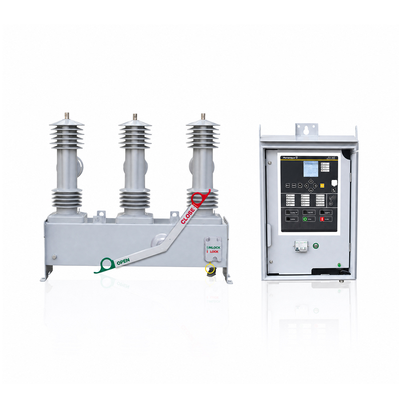
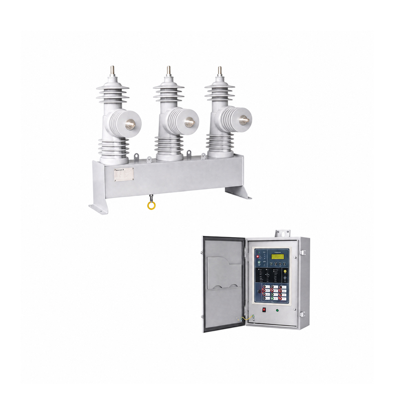
The controller is mounted in the control cubicle. Along with the controller, this cubicle also contains the auxiliary power supply with batteries for uninterruptible power supply, electronic boards and circuit breakers.
The controller contains a large number of protection functions (elements) which can be selected or deselected through the menu driven display.
Enhanced features
Analysis of current/voltage normal & negative sequence for power quality monitoring.
Recording of PQM with fault waveform of 128 sampling and 20 cycles.
Harmonics analysis of electric data.
Monitoring of Sag, Swell, Interruption, over & low voltage, unbalance and etc.
Improvement of fault detection algorithm.
Automatic isolation of faulted section site and interconnection with other healthy section.
Improved measuring accuracy
Multi-Protocol support. (DNP3.0, MODBUS,IEC60870-5-101/104 & IEC61850).
User programmable logic(PLC) support.
Cubicle
The cubicle includes the complete electronics, the protection relay and the UPS system of the recloser. Additional components and features can be selected via order.
General Protection Features
Operating sequence
Reclose times are selectable. The operating sequence is defined by:
O - 1st rt - CO - 2nd rt - CO - 3rd rt - CO
Reclose times
1st Reclose Time range: 0.3 - 600 sec
2nd Reclose Time range: 1.0 - 600 sec
3rd Reclose Time range: 1.0 - 600 sec
Timing resolution: 0.1 sec
Phase & Ground Fault
Pickup Level : 10~2000A (step:1A)
Fast TC Curve : 50 types (ANSI,IECmRecloser)
Fast Multiplier : 0.05~2.00 (step:0.01)
Fast Time Add : 0.00~1.00 (step:0.01sec)
Fast Min Response : 0.00~1.00 (step :0.01sec)
Delay TC Curve : 50 types (ANSI,IECmRecloser)
Delay Multiplier : 0.05~2.00 (step:0.01)
Delay Time Add : 0.00~1.00 (step:0.01sec)
Delay Min Response : 0.00~1.00 (step :0.01sec)
Direction Detection
3V1 threshold : 0~100% (step:1%)
3I1 threshold : 0~100% (step:1%)
3I1 Angle : 0~359° (step:1°)
High Current Trip (HCT)
Phase-HCT Pickup Leve : 25~10000A (step:1A)
Phase-HCT Adder : 0.01~1 (step:0.01sec)
Ground-HCT Pickup Leve : 25~10000A (step:1A)
Ground-HCT Adder : 0.01~1 (step:0.01sec)
Delay Time Current Trip
Phase-HCT Pickup Leve : 25~10000A (step:1A)
Phase-HCT Adder : 0.01~2 (step:0.01sec)
Ground-HCT Pickup Level : 25~10000A (step:1A)
Ground-HCT Adder : 0.01~2 (step:0.01sec)
Sensitive Earth Fault (SEF)
Pickup I0 : 0.1~20A (step:0.1A)
V0 : 10~80% (step:1%)
Operating Angle : 0~345° (1°step)
Opearting Time : 0.1~30 sec (step:0.1sec)
Cold Load Pickup/Inrush Restraint
Cold Load Phase Pickup Multiplier : 1.0~10 (step: 1)
Cold Load Time Duration : 0~180 min (step: 1 min)
Inrush 2nd Harmonic Level : 1~50% (step: 1%)
Phase, Ground, SEF Inrush Block : 1 ( yes) / 0( no)
Open Line (Loss of Phase) Detection
Voltage On Level : 50~90% (step: 5%) of rated voltage
Voltage Off Level : 35~75% ( step: 5%) of rated voltage
Delay Time : 0.1~30.0 sec (step: 0.1 sec)
Synchronism Check
Sync Fail Phase Difference : 5~60˚( step: 1˚)
Delay time : 0.1~30.0 sec (step: 0.1 sec)
Under Frequency
Pickup level : 47.00~59.98Hz (step:0.01Hz)
Delay Time : 0.03~10.00sec (step:0.01sec)
Over Frequency
Pickup level : 52.02~63.00Hz (step:0.01Hz)
Delay Time : 0.03~10.00sec (step:0.01sec)
Negative Sequence Overcurrent(Broken conductor)
Pickup I2 / I1 level : 30.0 ~ 100.0 (step: 1%)
I2 / I1 delay time : 0.01 ~ 100.0 (step : 0.01sec)
4 Setting Groups
Each group saves individual setting values
for different situations.
Active Setting Group Selection: 1~4
Inter lock
Live Load block
Sync fail block
General Protection Features
Recording
Events
Totally more than 32,000 events are stored and listed.
I/O events (1024) / Functional events (1024,30000) / System events(256)
Fault events (256) /PQM event(256) / Demand profile I,P,Q (6144) /Maximum demand profile (1024)
Fault Waveform
Up to 4 faults are stored. (32 samples/cycle, 240 cycles/record)
Graphical Display in Analysis Tool : Ia, Ib, Ic, In, Va, Vb, Vc
Load Profiling
Demand & Daily Maximum Current : Ia, Ib, Ic, In
Demand & Daily Maximum Power : kW, KVAR (A/B/C/3-ph)
Averaging Interval : 5 / 10 / 15 min
Graphical Display in Analysis Tool
Local / Remote : Control Position (only locally changeable)
Open/Close : Switch Body Status Change Command
DO (Direct Operate) and SBO (Select Before Operate) are supported.
Reset : Annunciator Manual Reset Command
Battery Test : Battery & Charger Circuit Check
Protection Function Blocking
User Configurable DO Points (reserved) : 2
Others
RTC (Real Time Clock) : YYYY/MM/DD hh:nn:ss
SOE (Sequence of Event) Time Resolution : 1 msec
Digital Filtering & Dead-band Setting for Analog Inputs
Calibration (Correction Factor) : Factory Setting only
Ia, Ib, Ic, In, Va, Vb, Vr, Vs, Vt
Factor Magnitude: 0.500~1.500
Phase Angle: 0.000~359.9°
Communication Interface
RS 232C #1
On FRTU left-side (inside the inner door)
SCADA or DA System Communication Interface
Through Cable / Wireless / Fiber Optic Modems
Functions
Remote Operation (Control, Status Monitoring, Tele-metering)
Remote Setting (optional)
File Transfer (Event & Fault Data; DNP protocol only)
Protocols
DNP 3.0 (Level 2) or IEC60870-5-101 (optional)
Baud Rate
1200 ~ 19200 bps
Address
Master Address: 0 ~ 65534
Slave Address: 0 ~ 65534
RS 232C Port #2
On FRTU Front Panel
Setting & Configuration, Maintenance, Recorded Data Analysis Through Setting & Analysis Tool
Functions
Setting and Configuration Change (Batch Job)
Protocol Monitor (Communication Frame Check)
Real-time Display : Measurement and Status Data
Event List and Fault Oscillograph
Demand Load Profiling & Graphical Display
FRTU Firmware Download
Protocols
Modbus
Baud Rate
1200~19200 bps
Connector Type
DB9 Female